ATLAS TRACKER PIXEL AND SCT - COOLING OF THE ELECTRONICS
Phase II - General description of the Compressor Unit and Operation
General Description | Instruction
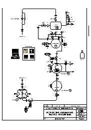
As described in the sketch the compressor unit is composed of a buffer tank 5, an oil-less 4 pistons compressor 1, a water cooled condenser 2, a storage tank 3 and a dryer unit 4.
The compressor 1 is equipped with inlet and outlet manometers M1a / M1b, by-pass electro valve EV1, outlet check valve CV1 and protected on high pressure by a switch automatic reset PA1. There is also a relief valve RV1 on the high side.
In addition we put temperature sensors on one of the cylinders Pt1, on the outlet of the compressor Pt11 and on the electrical motor PtM. We also installed an electrical fan F1 at the back of the motor.
The inlet of the compressor is protected by a 0.01 micron particles filter FR1.
We can isolate the compressor with the inlet manual valve MV1 and the outlet pneumatic actuated valve PV2. The compressor is set-up on vibration dampers and connected at the inlet and outlet with metallic flexible hoses (Ref. ASSIWELL 100 1.4541, DN25-1, LN500mm and DN50-1, LN600mm).
The condenser 2 is a standard shell-and-tube water-cooled Weaka type K20-100/8P. Its cold side is connected to water through a 3 ways electrical control valve EV2 and mechanical filter FR2. We added a relief valve RF2, a manometer M2, a temperature sensor Pt2 and a pressure transmitter PS2.
The horizontal storage tank 3 is a Weaka S25/10, 107 liters capacity. We put also a temperature sensor Pt3 and a proportional fluid level transmitter FL3.
Both condenser and storage tank are equipped with Rotalock valves at their inlet and outlet.
The storage tank is connected to the dryer unit with a pneumatic actuated valve PV2.
The dryer unit 4 is composed by 2 Danfoss DCR 0489 filter housing with removable molecular sleeve cartridge 48-DU of 0.8kg each. Each dryer is mounted on by-pass style with manual valves so we can work alternatively with one or the other one. As usual in the fridge circuit a sigh glass VT4 is connected at the outlet of the liquid side.
The buffer 5 is a 200 liters stainless steel tank. It is equipped with a manometer M5, a pressure sensor PS5, a relief valve RV5 and a temperature sensor Pt5. Inlet can be isolated with a manual valve MV5. There are additional valves for vacuum, bleeding and draining.
Most of these components are read or controlled by the control rack where we have:
A PLC Schneider Premium: Technical characteristics.pdf
Processor PMX P57 452M (TSX with 10 control channels)
Analogue input module:
TSX EAY 1600 - 16 channels 0-10V
TSX AEY 414 - 4 channels temperature sensors
Analogue output module:
TSX DEY 32D2K - 4 channels 0-10V
Discrete input module:
TSX DEY 32D2K - 32 channels
Discrete output module:
TSX DSY 32T2K - 32 channels 24V / 0.5A
2 PID Controller RCK REX G9: Technical characteristics.pdf
An inverter OMRON Sysdrive 3G3HV 15kW that controls and protects the motor of the compressor.
Finally we have a PC running the Schneider PLC via PL7PRO with its monitor that allows to control and to read the different phases and parameters of the compressor unit.
Currently from the desktop we can:
Control the different operating modes: STOP, STAND-BY and RUN
Read and display the different parameters of the compressor unit:
Condenser pressure from PS2
Buffer pressure from PS5
Compressor power and frequency from the inverter
Cylinder temperature from Pt1
Temperature of the electrical motor of the compressor from PtM
Condenser temperature from Pt2
Buffer temperature from Pt5
Level of liquid C3F8 inside the storage tank 3 through FL3.
Make a RESET of the different alarms.
Piping and Fitting:
Aspiration side (C3F8 gas inlet buffer tank) on the compressor unit: Flange DN50 PN10, Stainless steel.
Outlet side (C3F8 liquid outlet dryers) on the compressor unit: Flange DN20 PN10, Stainless steel.
Gasket on stainless steel flange DIN: We use spiral wound gasket Type LG-13 from Leader Gasket
Piping from the compressor unit to the distribution racks made with multilayer pipes PEXAL and crimp fittings: Ø42/50mm for gas line and Ø20/26mm for liquid line.
Safety and Protection
High pressure side of the compressor 1, the condenser 2 and the buffer tank 5 are protected by relief valves, respectively RV1, RV2 and RV5.
Outlet of the compressor is protected by a check valve CV1 to avoid return of liquid in the cylinders.
High pressure side of the compressor 1 is controlled by a pressure switch automatic reset PA1. The compressor will go to STOP mode if the pressure exceeds 12 bar.
A minimum admissible cylinder temperature is setting up at 40°C. The by-pass valve EV1 will not close as long as the temperature exceeds this limit.
A maximum admissible cylinder temperature is setting up at 65°C. The compressor will go to STAND-BY mode for 2 mn and to STOP after 5mn if the temperature exceeds this limit.
If the temperature of the motor exceeds 40°C, the fan F1 starts to cool down the motor of the compressor and will stop if the temperature goes under 35°C.
A maximum admissible motor temperature is setting up at 60°C. The compressor will go to STAND-BY mode for 2 mn and to STOP after 5mn if the temperature exceeds this limit.
A minimum admissible temperature on the buffer 5 is setting up at 5°C. The compressor will go to STAND-BY mode for 2 mn and to STOP after 5mn if the temperature exceeds this limit.
A maximum admissible pressure on the buffer 5 is setting up at 1.8 bar.a. The compressor will go to STAND-BY mode for 2 mn and to STOP after 5mn if the pressure exceeds this limit.
A maximum admissible pressure on the condenser 2 is setting up at 10 bar.a. The compressor will go to STAND-BY mode for 2 mn and to STOP after 5mn if the pressure exceeds this limit.
The inverter features a lot of electrical protections (overload, overvoltage, grounding, etc...) for the motor of the compressor. See protective functions in Specifications of the 3G3HV Inverter.
Note: The current PLC software is in beta version and subject to change.
Principle
The function of the compressor unit is to compress gas C3F8 coming from the heat exchangers of the detector through the back pressure regulators and the buffer tank 5 at 9 [bar.a] inside the condenser 2. The gas is liquefied in the condenser and the liquid C3F8 goes to the storage tank 3. It then passes through the dryer unit 4 and feeds the pressure regulator in the distribution rack. Both aspiration and condensation pressure are controlled and monitored.
Operation
The PLC controls the 3 different modes when running the compressor unit. For instance we access to these controls via the PC's desktop and later we will access via the XBT (PLC's display)
STOP mode: This is the default mode of the PLC when switching ON the power.
The compressor is stopped.
Valves EV1, PV2 and PV3 are closed.
Control loop of pressure in the condenser is active (PID control via REX-G9).
Display of the different temperatures, pressure and level.
STAND-BY mode: Heating up sequence of the compressor, control of pressures and temperatures.
Control loop of the temperature in the cylinders is active: If this temperature is under 40°C the compressor 1 run on itself at 30 Hz with its by-pass valve EV1 open until the cylinders temperature reaches 40 °C to be sure to not have portion of liquid in the cylinders. PV2, PV3 and MV5 are closed. Then the compressor stops and will restart if temperature goes under 20°C.
Control loop of pressure in the condenser is active (PID control via REX-G9).
Control loop of the temperature of the motor is active (ON/OFF action).
Control of the pressure in the buffer (aspiration): If the pressure in the buffer 5 goes higher than 950 [mbar.a] the compressor will start, after 2 seconds EV1 will close and PV2 will open to empty the buffer. This is to avoid overpressure in the buffer tank. The compressor will stop when reaching 750 [mbar.a].
Display of the different temperatures, pressure and level.
RUN mode: The compressor is aspiring gas and liquid is circulating.
Like in STAND-BY mode, the control loops of the cylinder's temperature, of the condenser's pressure and of the motor's temperature are active.
Control loop of the pressure in the buffer (aspiration pressure) is active (PID control via REX-G9).
EV1 is closed and PV2 open in order to pressurize gas in the condenser 2 and send liquid in the storage tank 3.
The pneumatic valve PV3 is open to send liquid in the circuit. It will first go through the dryer unit 4 to remove possible moisture.
Valves of the dryer 4, MV1 and MV5 should be open.
Display of the different temperatures, pressure and level.
We have currently 5 regulation loops on the unit:
Condensation pressure: The gas C3F8 comes from the compressor 1 at 9 [bar.a] and around 60 °C. The condensation of the gas C3F8 occurs at constant pressure and temperature. An autotune PID controller REX-G9 measures the pressure with PS2 and controls the electrical 3 ways valve EV2 to adjust the flow of cooling water in the condenser. Pressure point is setting up on the controller.
Aspiration pressure: The speed - the frequency - of the compressor is controlled by the inverter, itself controlled by an autotune PID controller REX-G9 that takes signal from the pressure sensor PS5. So the unit has a constant aspiration pressure, independent of the gas flow coming from the detector. This regulation works from 1.0 to 1.5 [bar.a] and pressure point is setting up on the controller. We are currently limited by the compressor characteristics that give us a range from 30 to 60 Hz or 80 to 200 [g/s] for aspiration pressure between 1.0 and 1.5 [bar.a]. Note that 80 [g/s] gives around 7 [kW] cooling power.
Temperature in the cylinders: If this temperature is under 40°C (Pt1 sensor) the compressor 1 run on itself at 30 Hz with its by-pass valve EV1 open until the cylinders temperature reaches 40 °C to be sure to not have portion of liquid in the cylinders. PV2, PV3 and MV5 are closed. Then the compressor stops and will restart if temperature goes under 20°C.
Pressure in the buffer (aspiration): If the pressure (PS5 sensor) in the buffer 5 goes higher than 950 [mbar.a] the compressor will start, after 2 seconds EV1 will close and PV2 will open to empty the buffer. This is to avoid overpressure in the buffer tank. The compressor will stop when reaching 750 [mbar.a].
Temperature of the motor of the compressor: if the temperature ( PtM sensor) of the motor goes above 40°C the fan F1 starts. It will stop when the temperature goes under 35°C.
Starting Procedure
The connected piping system must be clean and gastight. Maximum leak rate is 1.10-3 [mbar.l/sec]. See Leak check and cleaning procedure adopted for ATLAS phase II
If never done before the compressor unit and the connected system are emptied down to 0.05 [mbar] using an oil free diaphragm vacuum pump connected to the buffer tank 5 or on the Schrader connectors on the appropriate Rotalock valves, depending of presence or not of Liquid C3F8 in the storage tank 3. Once done the compressor unit can be isolated with the manual valve MV5 and the dryer unit 4 valves, that means that each new connected piping should have its own connector for vacuum process.
Control that the cooling water is well circulating to the condenser.
Depending of the status of the connected circuit, open MV1 and MV5.
To start the compressor just press the button p to have" RUN" on the desktop. All the regulation loops will be active and the compressor will run on itself, with the by-pass valve EV1 open until it reaches 40°C. This sequence takes about 8 mn.
Then the by-pass valve EV1 closes and the pneumatic valves PV2 and PV3 automatically open leaving the compressor compressing gas inside the condenser and liquid in the tank. As described above, the condensation pressure is controlled by a PID controller REX-G9 technical characteristics.pdf acting on an electrical 3 ways valve to regulate the flow of cooling water. The pressure is setting at 9 bar.a (meaning around 27°C). To change this value press PARA twice to have the message "Setting Values (SV)" on the display, then press q or p to set the new value and that's all. Note that the measured-value display (PV) is in green and that the set-value display (SV) is in red. If necessary one can starts an auto-tuning sequence to have the optimum PID constants. To do that press a few times MODE to have "PID>>>AT? *(PID CONTROL)" on the message display, then press >>> to start auto-tuning. When auto-tuning ends, the operation automatically returns to PID control action. For more information on the REX-G9 functions go to the instruction manual.pdf.
If MV5 is closed the compressor will aspire gas in the buffer tank until it reaches the limit of 750 [mbar.a.]. ON/OFF regulation will be active between 750 and 950 [mbar.a]. Pressure range of 1.0 to 1.5 [bar.a] in the buffer tank is controlled by the second REX-G9 that will speed up the compressor if the pressure is above the set-point. To change the value proceed as explained above. This regulation is limited by the compressor range of 30-60 Hz and the characteristics of the connected circuits (pressure regulator, expansion device, exchanger, back pressure regulator). Note that one should not closed MV5 as PV3 are open.
So normally MV5 is open to let the compressor aspires in the connected circuits and liquid is sending in the same circuits. Open or close the dryer's valves in order to go through at least one.
If one want to stop the circulation of liquid C3F8 go to STAND-BY mode in order to close PV3 and keep the control of the pressure in the buffer tank; the compressor will recover all the vapor in the circuits.
(to be continued)