Liquid cooling systems: Leakless v.2
ATLAS CALORIMETERS / LAYOUT OF COOLING SYSTEMS & PIPING
IN UX15
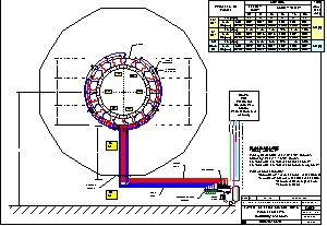
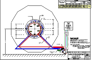
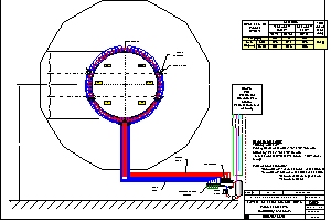
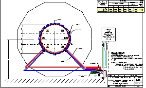
Drawings 186.5.08, 186.5.09, 186.9.18 and 186.9.20 show the current
layout of the cooling systems and their piping for the ATLAS Calorimeters
-LAr and Tile - in UX15. The cooling stations, consisting of the tank,
circulator, heat exchanger and pneumatic pressure regulators are located
on the floor of the cavern. The pipes can go up to ~ 15 m to distribute
the liquid in the heat exchangers on the electronics. The detectors are
divided in 6 sectors with the aim to have a pressure head of 2 to 3m in
each sector. Each sector has a pressure transmitter and an isolating valve
and will feed 8 or 12 drawers for the tile calorimeter and 2 or 3 crates
for the LAr calorimeter.
According to the LCS v.2 principle, the overpressure (1 to 2 bar) will
be limited to the inlet pipes, from the pump at the cooling station to
the arrival in the corresponding sector. The distribution lines in the
sectors, the heat exchangers in the electronics and the return pipes will
run in sub-atmospheric mode (0 to -700mbar).
LAr Calorimeter
Tile Calorimeter
 Back to ST/CV Cooling of Detectors Home Page
CERN/P.BONNEAU/21/05/2001
Back to ST/CV Cooling of Detectors Home Page
CERN/P.BONNEAU/21/05/2001