CONCEPTS OF REFRIGERATION CIRCUIT DESIGN FOR CMS TRACKER COOLING

S. Grohmann
CERN, ST-CV

Abstract
This paper contains three alternative technical proposals for the design of the CMS tracker cooling system between the C6F14 cooling racks in UXC 55 and the primary ST-CV installations in the service cavern. Design data of the systems and their components and control strategies are presented.
 

    1. INTRODUCTION

    This paper is intended to demonstrate and compare solutions for the refrigeration circuit design for the CMS tracker cooling at an operating temperature of -20 °C using industrial standard equipment. It concerns installations between the primary ST-CV water circuits and the C6F14 liquid cooling racks. The paper contains a preliminary design of the main components, piping and control.

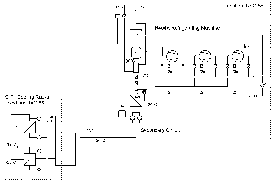
    General space conditions in the CMS experimental and service caverns are shown in figure 1 and figure 
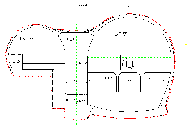
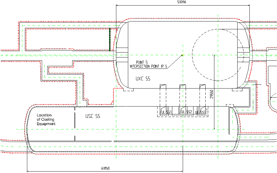
2. The area for cooling and ventilation services is situated at the left end of USC 55 (figure. 2). Services are provided to the experimental cavern through the access tunnels UL 551 … UL 553. The C6F14 cooling racks are located in UXC 55 beside the experiment at the inner and outer side of the tunnel circumference.
    The maximum distance between the locations of cold generation (USC 55) and cold consumption (UXC 55) is about 120 m horizontal and 12 m vertical.

    Because of the long distance between the installations a decision has to be taken whether a direct evaporation circuit or a secondary circuit system shall be installed. Although this is basically a question of economic optimization some technical peculiarities have to be considered as well.

    The advantage of the direct evaporation system is that temperature differences to a secondary circuit can be avoided and fluid and suction line don't have to be insulated (the installation of an internal heat exchanger provided).
    On the other hand, pressure drops, especially in the suction line, have a considerable influence to the efficiency and special measures have to be taken to guarantee a safe oil return and lubrication of the compressors.
    Direct evaporation systems with distances of 50 … 80 m are industrial standard applications, e.g. in supermarkets and cold stores. The extension to about 120 m for CMS tracker cooling doesn't affect the technical solution as long as recommended velocities and resulting pressure drops lead to a reasonable result.

    The advantage of secondary circuit systems is that the refrigerating machine can be designed as a compact unit and the hydraulic design of the secondary circuit is as easy as for heating systems, which is particularly favorable in part-load operation.
    However, additional temperature differences and pumping capacity are not negligible in terms of efficiency and all secondary fluid pipes have to be insulated.

    In the following chapters basic design parameters of 3 alternative concepts are presented in order to identify an optimum technical solution.


    2. GENERAL DESIGN PARAMETERS

    The general design parameters for the CMS tracker cooling system are shown in table 1.
     
    Table 1 - General Design Parameters
    Refrigeration Capacity 50 kW
    Modularity (No. of Racks in UXC 55) 2
    Working Fluid C6F14
    Inlet / Outlet Temperatures -17 / -20 °C
    Heat Sink Water
    Inlet / Outlet Temperatures 13 / 19 °C
     

    3. DIRECT EVAPORATION SYSTEM

      3.1 Circuit Layout
      The cooling circuit layout is shown in figure 3 . The condensing unit is located in USC 55, the two evaporating units are situated within the C6F14 liquid cooling racks in UXC 55.

      The compressor group consists of e.g. 3 compressors operating in parallel.
      The common discharge line leads to an oil-separator / oil-receiver. The combination of oil-separator and liquid level controlled oil-receiver guarantees the safe lubrication of the compressors at any operating condition.
      The pressurized refrigerant is condensed in a water-cooled condenser. The liquid is accumulated in a refrigerant receiver that operates under saturation conditions and balances different heat exchanger fillings at varying operating conditions. The downstream water-cooled heat exchanger provides sub-cooling to avoid boiling caused by pressure drops in the fluid line.
      Inside the C6F14 cooling racks, which are thermally insulated and vapor-tight, the refrigerant is further sub-cooled by the internal heat exchanger before it is expanded to the evaporating pressure / temperature and injected into the evaporator. After dry evaporation (superheating) the suction gas is further superheated above the cavern dew point at the other side of the internal heat exchanger before it enters the suction line in the cavern.

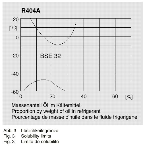
      The suction line is designed to ensure the return of the oil fraction that is not separated and therefore circulating in the circuit (usually <<1 %). The oil is transported as a film at the inner tube surface and in form of small drops in the vapor stream. The transport, especially in vertical parts, requires a minimum vapor velocity of 7 … 12 m/s and appropriated oil with low viscosity at the operating temperature (see chapter 3.2). In addition, horizontal tube sections are laid with a declination of about 5 % and vertical sections can be split (parallel tubes with different cross-sections) to assure minimum speed at part-load operation. Another safe solution is to install an oil-trap at the bottom of the 12 m vertical section. From there the oil is returned to the oil-receiver by a float-controlled pump in a discontinuous way.

      3.2 Working Fluid and Lubricant
      The direct evaporation system works with the HFC R404A as refrigerant. It has been developed as a substitute for R502 and is commonly used in low-temperature applications. R404A is a zeotropic mixture (44 % R125, 52 % R143a, 4 % R134a) with a normal boiling point of –46.4 °C and a very moderate temperature glide of about 0.7 K.
      Although the component R143a is flammable R404A doesn't form an ignitable mixture in air.
      Physiological properties are determined by the components of the mixture. There are no specific effects on the human organism. The threshold limit value at place of work (TLV) is 1000 ppm. Respiratory disturbance occurs from a concentration in breathing air of about 20 % on. R404A vapor is heavier than air so that higher concentrations can crop up at low level.

      Synthetic ester oils (polyolester) have been developed as lubricant for HFC blends. These oils do not mix with R404A over the whole application range (see figure 4). However, they have no solubility limits within the evaporating temperature range, which is important for the oil return in the suction line. The solution of refrigerant in the oil reduces its viscosity and improves its flow behavior.

      The total refrigerant charge for the direct evaporation system is approximately 100 … 130 l. The oil charge is in the order of 50 … 100 l.

      3.3 Design of Main Components & Piping
        3.3.1 Compressor Group
        The compressor group consists of e.g. 3 compressors in parallel operation. General design guidelines for the piping arrangement of compressor groups have to be followed.

        The choice of the compressor technology depends basically on the delivery capacity (compressor displacement) that is required. Typical ranges of scroll, piston and screw compressors are given in table 2.
         

        Table 2 - Capacity ranges of scroll, piston and screw compressors (manufacturer data from Copeland and Bitzer)
        Compressor delivery capacity [m3/h]
        Scroll (hermetic)
        Piston (semi-hermetic)
        Screw (semi-hermetic)
        8 … 35
        6 … 300
        85 … 250
        Taking into account operating conditions and pressure drops (see chapters 3.3.2 and 3.3.3 ) a nominal delivery capacity of about 210 m3/h is needed. Sharing out among three compressors with 70 m3/h each leads to the classical application range of piston compressors. Small screw compressors are suitable as well. Scrolls are too small for this application since a group of at least 6 compressors would be needed.

        The number of compressors should be chosen as a function of the minimum capacity requested and the minimum part-load operation of the special compressor type. Common solutions for compressor capacity control are cylinder shut off, pole changing control and frequency conversion. The minimum part-load operation has to be studied in a detailed design.
        Speed control via frequency conversion should be applied for a smooth adaptation of capacity.

        3.3.2 Heat Exchangers
        A preliminary design of heat exchangers has been done using design software for Alfa Laval plate heat exchangers. The results are presented in table 3.
         
        Table 3 - Preliminary design of heat exchangers (specification for Alfa Laval plate heat exchangers)
         
        Condenser
        Sub-cooler
        Evaporator
        internal HX
        Cold Fluid
        Water
        Water
        R404A
        R404A
        Inlet / Outlet Temperature [°C]
        13 / 19
        13 / 19
        -30 / -22
        -22 / 18
        Mass Flow Rate [kg/s]
        3.103
        0.010
        0.163
        0.163
        Operating Pressure [bar]    
        2.07
        2.07
        Pressure Drop [kPa]
        98.3
        3.13
        8.35
        46.0
        Hot Fluid
        R404A
        R404A
        C6F14
        R404A
        Inlet / Outlet Temperature [°C]
        107 / 30
        30 / 25
        -17 / -20
        25 / 1
        Mass Flow Rate [kg/s]
        0.326
        0.326
        8.480
        0.163
        Operating Pressure [bar]
        14.3
        14.3
         
        15.0
        Pressure Drop [kPa]
        6.64
        31.3
        147
        0.5
        Capacity [kW]
        78.1
        2.5
        25.1
        5.7
        Type (Alfa Laval) / No. of Plates
        CB52 /52
        CB26 /6
        CB52-X /92
        CB52-X /28
        Heat Transfer Area [m2]
        2.5
        0.1
        4.6
        1.3
        Height [mm]
        526
        311
        526
        526
        Width [mm]
        112
        112
        112
        112
        Depth [mm]
        135
        24
        231
        78
        The application of plate heat exchangers, especially as evaporators, is recommended because of their compact design. The water-cooled condenser might be planed as a shell-and-tube heat exchanger as well.
        On the other hand, plate heat exchangers seem to be unsuitable for the internal heat transfer because of unfavorable flow conditions and high pressure losses at the suction side (see also chapter 3.3.3 and figure 5). The application of finned (coaxial) heat exchangers should be considered instead.
        3.3.3 Piping
        The design of tube dimensions and pressure drop calculations have been done for the fluid and suction line.
       
        The results for the fluid line are shown in table 4. Geometrical conditions and a number of fittings and additional resistances were taken into account. In general, velocities should be in the range of 0.4 … 1 m/s in order to avoid the risk of boiling caused by pressure drops.
        The static pressure rise due to the height difference of 12 m leads to a total pressure increase between sub-cooler and internal heat exchanger.
         
      Table 4 - Design parameters of the fluid line
      Mass Flow Rate 0.326 kg/s
      Length 120 m
      Height Difference 12 m
      No. of Bends 20
      Additional z-Value 20
      Diameter 28 mm
      Velocity 0.5 m/s
      Dynamic Pressure Drop 0.271 bar
      Static Pressure Drop -1.230 bar
      Total Pressure Drop -0.959 bar
       
        The results for the suction line are shown in table 5. A minimum part-load operation of 12.5 % was assumed. A number of tube components like fittings, valves and a filter were also taken into account.
        In contrast to low velocities in the fluid line, the suction gas velocity has to be in a range of 7 … 12 m/s to guarantee safe oil return. The installation of split suction lines to overcome vertical sections would only be necessary inside the experimental cavern (tube dimensions are given in table 5 for this case). Considering the location of the liquid cooling racks it seems however possible to avoid rising parts in this area (figure 1). At the bottom of the 12 m height difference between the access tunnel and USC 55 an oil-trap and a float-controlled pump could be installed as indicated in figure 3.
       
        The total saturation pressure drop in the suction line of 0.265 bar is reasonable for this kind of installation. The more sensitive part is the design of the internal heat exchanger as can be seen from the process conditions marked into the R404A lg p, h - diagram in figure 5.
         
      Table 5 - Design parameters of the suction line
      Mass Flow Rate 0.326 kg/s
      Min. Part-Load Operation 12.5 %
      Length 120 m
      Height Difference 12 m
      No. of Bends 20
      No. of Valves 2
      No. of Filters 1
      Additional z-Value 50
      DN Horizontal Tube 89 mm
      Velocity Horizontal Tube 9 m/s
      DN Vertical Tube 1 80mm
      Velocity Vertical Tube 1 10 m/s
      DN Vertical Tube 1 28 mm
      Velocity Vertical Tube 1 6 m/s
      Pressure Drop 0.265 bar
      Saturation Temperature Drop 3.5 K
       
      3.4 Control
      The variables to be controlled are capacity, evaporation (superheating) and condensation pressure.
     
      The condensation pressure is controlled by the flow rate of cooling water. It has to be controlled in order to avoid too low condensation temperatures in part-load operation. Low condensation pressure could cause insufficient mass flow through the expansion valves and a low fluid temperature could lead to temperatures at the suction line below the dew point (internal heat exchange).
     
      Dry evaporation of the refrigerant is controlled by thermostatic expansion valves, which are mechanical devices. The temperature of superheated vapor is transformed into pressure in a sensor that is installed at the evaporator outlet. This pressure is transmitted to the valve and works against a spring. The balance of pressure force and spring force determines the position of the needle.
     
      The capacity of the system is controlled by the compressor speed respectively the cut-in / cut-out of compressors or cylinders depending on the C6F14 inlet temperature (-17 °C). The compressor speed is preferably controlled by frequency conversion.
      However, the refrigerating capacity can only be adapted to one of the two C6F14 racks. The evaporating temperature of both systems will be the same, but since one system could run with nominal power and the other one in part-load mode the C6F14 temperatures in both racks could be different (different DT in heat exchanger at different power). The solution of this problem would require a higher effort of control.

    4. SECONDARY CIRCUIT WITH LIQUID COOLANT

      4.1 Circuit Layout
      The secondary circuit layout is shown in figure 6. A compact R404A refrigerating unit is located in USC 55. The refrigerating capacity is transferred to a secondary circuit that works with a liquid coolant and transports the 'cold' to the experimental cavern.

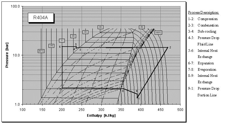
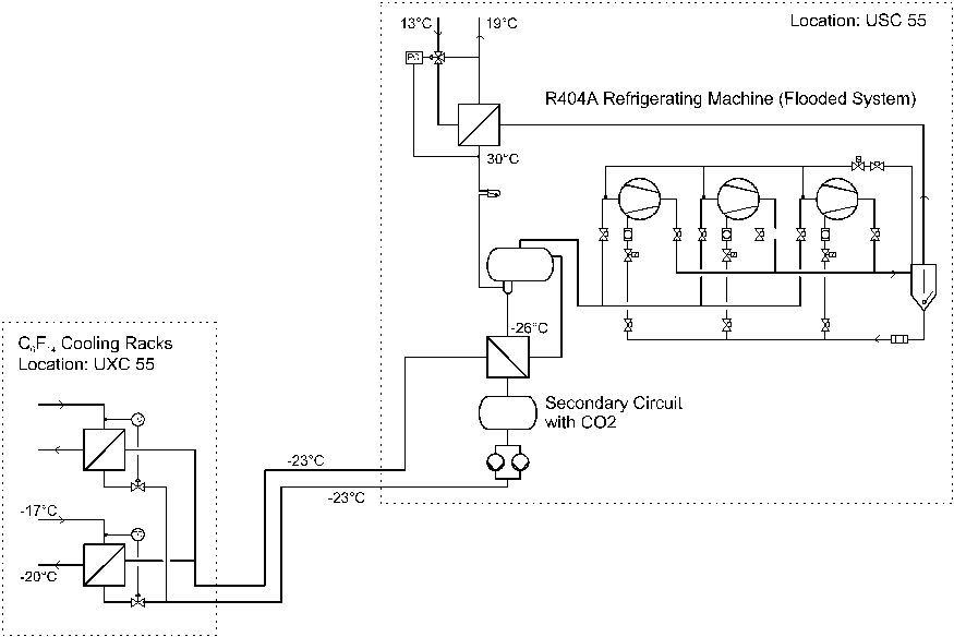
      The R404A unit works with dry evaporation. In contrast to the direct evaporating circuit the installation of an oil-separator is only necessary if screw compressors are used. Further, the installation of an internal heat exchanger doesn't have any advantage.

      The liquid coolant is cooled in the R404A evaporator and pumped to the racks in UXC 55 where it cools the C6F14 in a liquid / liquid heat exchanger. Pipe temperatures are below the dew point and have to be insulated for that reason.

      4.2 Working Fluids
      Working fluids for the refrigerating machine are the same as for the direct evaporating circuit. Because of the compact design the R404A charge can be considerably reduced to about 15 … 30 kg. The oil charge depends basically on the choice of compressor technology (piston or screw) but is in any case lower than for the direct evaporating system.

      Liquid coolants for low temperature applications can be brines, aqueous solutions of alcohol or organic carbon compounds.
      Calculations have been done with the product Ò PEKASOL 50, which is a brine of organic salts. It is commonly used and combines good thermodynamic properties with corrosion protection, environmental compatibility and foodstuff unobjectionability. A solution of 80 Vol.% in water is frost-proof until –34°C.
      With respect to the tube dimensions (see 4.3.3 ) the total charge of cooling brine is about 850 l.
      Other secondary fluids like Ò TYFOXIT, which is potassium formiate based, could be used as well.

      4.3 Design of Main Components & Piping
        4.3.1 Compressor Group
        The compressor group can be designed in the same way as described in chapter 3.3.1 . Because of different operating conditions the nominal delivery capacity is reduced to about 190 m3/h.
        In case piston compressors are used the compact unit can be designed without any oil separator and oil supply. However, these installations are necessary for the operation with screw compressors.
        4.3.2 Heat Exchangers
        A preliminary design of plate heat exchangers is shown in table 6. The condenser could also be planned as a shell- and tube heat exchanger. The sub-cooler can possibly be omitted.
         
        Table 6 - Preliminary design of heat exchangers (specification for Alfa Laval plate heat exchangers)
         
        Condenser
        Sub-cooler
        Evaporator
        Liquid Cooler
        Cold Fluid
        Water
        Water
        R404A
        Pekasol 50
        Inlet / Outlet Temperature [°C]
        13 / 19
        13 / 19
        -34 / -26
        -25 / -22
        Mass Flow Rate [kg/s]
        3.187
        0.081
        0.439
        2.607
        Operating Pressure [bar]    
        1.77
         
        Pressure Drop [kPa]
        57.9
        0.8
        11.0
        31.7
        Hot Fluid
        R404A
        R404A
        Pekasol 50
        C6F14
        Inlet / Outlet Temperature [°C]
        56 / 30
        30 / 27
        -22 / -25
        -17 / -20
        Mass Flow Rate [kg/s]
        0.439
        0.439
        5.214
        8.480
        Operating Pressure [bar]
        14.5
        14.3
           
        Pressure Drop [kPa]
        21.7
        22.6
        32.7
        94.7
        Capacity [kW]
        80.2
        2.0
        50.2
        25.1
        Type (Alfa Laval) / No. of Plates
        CB300 /10
        CB26 /6
        AC120-EQ /94
        CB200 /21
        Heat Transfer Area [m2]
        2.2
        0.1
        8.7
        4.2
        Height [mm]
        990
        311
        617
         
        Width [mm]
        365
        112
        192
         
        Depth [mm]
        42
        24
        274
         
         
        4.3.3 Piping & Pumps
      Calculations of tube dimensions and pressure drops have only been done for the secondary circuit. Pipe dimensions for the compact R404A unit are roughly the same as presented in chapter 3.3.3 and pressure drops are comparatively small because of short distances.

      The hydraulic design of the secondary circuit, as shown in figure 6, comprises design of tube dimensions for the supply and return line to UXC 55 (section 1) and the supply and return lines to the C6F14 cooling racks (section 2).

      Results of the pressure drop calculation and performance data for the pump are presented in table 7.
       

      Table 7 - Design parameters of the secondary circuit (working fluid: Ò PEKASOL 50, 80%)
       
      Section 1
      Section 2
      Volume Flow Rate 15 m3/h 7.5 m3/h
      Pressure Drop Heat Exchanger 32.7 kPa 31.7 kPa
      Tube Length 240 m 10 m
      No. of Bends 20 4
      No. of Valves 3 3
      Additional z-Value 100 20
      Diameter DN 64 DN 42
      Velocity 1.3 m/s 1.5 m/s
      Total Pressure Drop 6.04 bar
      Pump Pressure Head 50 m
      Pump Capacity 3.2 kW
      In contrast to the direct evaporating circuit all tubes of the secondary circuit have to be insulated to avoid condensation. Calculations have been done with ARMAFLEX, which is the standard insulating material in refrigeration.
      The results are shown in table 8. The main tubes DN 64 are insulated with a layer of 15 mm. Long-term stability with an increased humidity of the insulation material for an operation of 10 years is proven as well.
       
      Table 8 - ARMAFLEX insulation of the secondary circuit
      Ambient Temperature / Humidity 26.0 °C / 40 %
      Dew Point Temperature 11.3 °C
      Line Temperature -25.0 °C
      Thermal Conductivity - Insulation 0.0361 W/mK
      Surface Coefficient - External 9.0 W/m2K
      Recommended Insulation Thickness 9 … 12 mm
      Insulation Thickness 15 mm
      Surface Temperature 16.7 °C
      Heat Losses 6.7 kW
      Results after 10 Years:  
      Thermal Conductivity – Insulation 0.0464 W/mK
      Surface Temperature 14.6 °C
      Heat Losses 8.3 kW
      4.4 Control
      The control of the R404A unit works in the same way as described in chapter 3.4. The refrigerating capacity is controlled according to the secondary fluid inlet temperature into the R404A evaporator.
     
      The design of the secondary circuit with differential pressure controlled by-pass makes sure that the system runs in a stable mode under any full or part-load condition. The flow rates through the liquid / liquid heat exchangers in the racks are regulated according to the C6F14 inlet temperature. The system guarantees a precise control of temperatures in both C6F14 circuits.
      The installation of variable flow pumps is also possible.
       

    5. SECONDARY CIRCUIT WITH CO2

    Following recent developments the usage of CO2 as secondary fluid can combine advantages of direct and indirect circuits as shown in table 9.
Table 9 - Advantages of secondary circuits with CO2
Advantages in Comparison to
Direct Evaporating Circuit
Conventional Secondary Circuit
  • No oil return,
  • stable part-load operation,
  • "simple" hydraulic design.
  • Stable evaporating temperature (no glide),
  • usage of latent heat,
  • smaller pumps, tubes, heat exchangers.
  •  
    The use of these advantages requires, however, a higher effort of installations but economic viability in comparison to conventional secondary circuits can be achieved in this capacity range.
        5.1 Circuit Layout
        The circuit layout is shown in figure 7. In contrast to the first two solutions the R404A circuit works with a flooded evaporator, which allows smaller temperature differences. Boiling CO2 is pumped to the C6F14 cooling racks where it evaporates partially. The circulation ratio corresponds to a quality of about 50 % vapor in the return line. The CO2 vapor is re-condensed in the R404A evaporator.
        5.2 Working Fluids
        CO2 is a natural fluid that can be in liquid form within a temperature range of  –56.6 … 31.1 °C at pressures higher than 5.2 bar. Liquid CO2 cannot exist at atmospheric pressure.
        CO2 is not flammable, color-, odor- and tasteless. The gas is about 1.5 times heavier than air.

        Important concentration thresholds are:
        - normal concentration in air: 0.03 Vol.%
        - headache / respiration disturbance: 3 … 5 Vol.%
        - cramps / faint: 8 … 10 Vol.%
        - TLV: 0.5 Vol.%

        With respect to the tube dimensions (see chapter 5.3) and the receiver volume the total CO2 charge is about 150 kg.

        5.3 Design of Main Components & Piping
        Because of the operation with smaller temperature differences (higher evaporating temperature) the delivery capacity of the R404A compressor group can be reduced to about 140 m3/h.

        The water-cooled condenser can be designed as shell-and-tube heat exchanger, the flooded evaporator as plate heat exchanger. The R404A receiver-separator unit is a specially designed pressure vessel.

        Tubes of the CO2 circuit can be considerably smaller in comparison to the conventional secondary circuit. Assuming average velocities of 2 m/s the diameter of the supply line can be reduced from DN 64 to DN 15 and the return line from DN 64 to DN 20.

        Insulation of tubes is necessary to avoid condensation. The thickness of the material is 13 mm (compare to table 8).

        The pump capacity is reduced proportionally to the flow rate of the secondary fluid (assuming same pressure drops in the system). This means a reduction to less than 10 % of the pump capacity that is needed for the conventional secondary circuit.
        The appropriate pump technology for this kind of application is side-channel pumps. They are self-priming, have extremely low NPSH values and are able to handle two-phase flow with up to 50 % vapor. A suction head >1 m is required, however.

        5.4 Control & Safety
        The control of the flooded R404A system works a bit differently in comparison to dry evaporation. A high-pressure side float control valve expands the refrigerant from condensation pressure into the receiver-separator unit. Evaporator and receiver-separator unit work on the thermo-syphon principle. The capacity (compressor speed) is controlled according to the CO2 receiver pressure.
    The control of the CO2 circuit is done in a similar way to the standard secondary circuit. Flow rates through the C6F14 heat exchangers are adapted according to the C6F14 inlet temperature. Variable flow pumps or a by-pass system as described in figure 6 could be applied.
    The safety system for the CO2 circuit needs special care. The maximum pressure is limited to 25 bar, which allows the use of standard components. This pressure corresponds to a saturation temperature of about –11 °C.
    In case the cold generation fails the CO2 pressure rises continuously. As the pressure reaches the set-point of the safety valve the circuit is constantly emptied through a relief line until only superheated CO2 vapor remains. This might be the biggest disadvantage of the system, especially for machines in stand-by mode that might be installed for redundancy reasons.
    In addition, CO2 detectors in combination with warning and alarm devices have to be installed in the tunnel area.

      6. REDUNDANCY

      The CMS tracker cooling system has to be equipped with redundancy to avoid any temperature rise above 0 °C.

      In a refrigerating machine there are a couple of factors that could cause a failure of the system. Standard components normally have a high reliability but their MTBF values (mean time between failures) have to be considered, nevertheless. On the other hand, the loss of refrigerant caused by leaks, which is at least not unusual, is not affected by the components themselves. The implementation of e.g. additional compressors or control valves in the same circuit wouldn't lead to any redundancy in this case.

      This example illustrates that the design of a redundant system has to be done in a careful way taking into account specific component and system parameters as well. Further studies are necessary in this field.

      7. SUMMARY

      A basic design of the cooling system for CMS tracker cooling has been done. Design data for three alternative proposals are presented. Each system has advantages and disadvantages in terms of full- and part-load operation, control, space requirements, insulation, investment and operating costs (not treated in this report) and safety.
      A comparison of this technical solutions based on the figures presented should be possible in order to identify an optimum solution for the final design.

    APPENDIX 
      
    Fig. 1: CMS experimental and service cavern, cross-section 

     
    Fig. 2: CMS experimental and service cavern, longitudinal view 
      
    Fig. 3: Direct evaporation circuit 

     
    Fig. 4: Solubility limits for polyolester oil and R404A 
    Fig. 5: R404A lg p / h –diagram, conditions at different points of the refrigerating circuit 
    Fig. 6: Secondary circuit with liquid coolant 

     
    Fig. 7: Secondary circuit with CO2

     
      Back to EST/SM/SF Page